
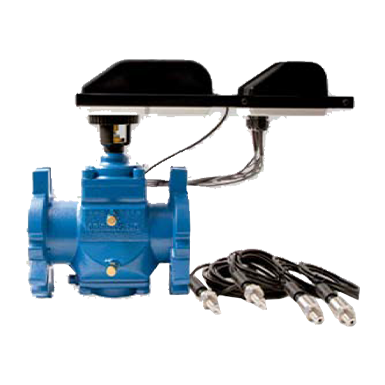
Description
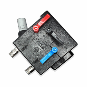
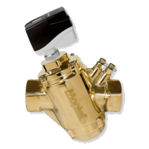
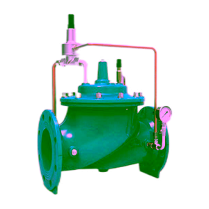
The Maplef Energy FIT System measures energy usage while monitoring coil performance to adjust a PICV to- optimize coil performance. The PICV maintains the correct flow despite pressure changes and guarantees the flow and actuator position only change when demand requirements change or ΔT is outside of specification. The pressure sensors measure upstream and downstream pressure allowing the BMS to reduce system pressure to save pump energy when pressure drop is higher than the PICV’s requirements. The Maplef Intelligent Interface calculates the BTU and displays the data via Bluetooth® on an Android or iPhone mobile device or sends it back to the BMS via BACnet communications. The Maplef Energy FIT System is fully customizable and allows selection of components that work best to optimize the application’s unique energy goals.
Specification
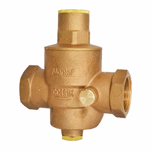
Maplef PICV valve:
Static pressure: 4000 kPa / 580 psi
Ambient temperature: -10°C to +50°C / +14°F to +122°F
Media temperature: -20°C to +120°C / -4°F to +248°F
Material:
Housing and covers: Ductile iron ASTM A395 Grade 60-40-18
Stem seals: EPDM
O-rings: Nitrile
Flow regulation unit: 316 Stainless steel
Diaphragm: Hydrogenated acrylonitrile-butadiene-rubber
Stroke: 2160° (FIT6: 3600°)
Maximum close off pressure: 800 kPa / 116 psi
Maximum operational ΔP: 800 kPaD / 116 psid
Maximum allowable operating
pressure: 1600 kPaD / 232 psid
Control characteristic: Linear flow
Control range: 1:800 / IEC 60534
Rangeability: >100:1
Turn down ratio: 228:1
Shut-off leakage: ANSI / FCI 70-2 2006 / IEC 60534-4 – Class IV
Flow rate range: 1.48-76.8 l/sec / 23.4-1220 GPM
End connection: Universal flange connections which can be used with both
ISO and ANSI flanges.
Mounting kits are not supplied by Maplef
Housing taps: 1/4” ISO
Maplef PICV actuators1:
Maplef MSM.0.0.0.3 (standard)
Maplef MSM.0.0.0.4 (standard failsafe)
Maplef MSM.0.0.0.5 (BACnet)
Maplef MSM.0.0.0.6 (BACnet failsafe)
Supply voltage: 22-26V AC, 50/60 Hz or 22-26V DC
Type: Electrical, Bi-directional synchronous motor
Power consumption: 12VA. For failsafe versions: 25VA (peak)
Control signal: 2-10V DC
Resolution: 1:800 (2-10V)
Feedback: 2-10V DC
Control mode: Linear flow
Failsafe function: Yes (MSM.0.0.0.4 and MSM.0.0.0.6)
Manuel override: Yes
Position indicator: No
Operation time: FIT.3-5: 190 sec (from closed to fully open valve)
FIT.6: 317 sec (from closed to fully open valve)
Ambient temperature: -10°C to +50°C / +14°F to +122°F
Humidity rating: 5..95% rH, no condensation
Housing material: UL94 V0-rated plastic
Protection: IP54 including upside-down mounting
CE conformity: EN 60730, class II
Programming: Programming of all settings on interface with buttons and
display or via BACnet
Cable: Fixed, 5 wires x 0.80 mm2, halogen free, 1 meter
Fixed, 5 wires x AWG18, halogen free, 3 ft
Additional for BACnet versions:
Fixed, 3 wires x 0.80 mm2, halogen free, 1 meter
Fixed, 3 wires x AWG18, halogen free, 3 ft
Calibration: Automatic at startup
Valve-actuator coupling: Easy snap coupling
BACnet device profile: BACnet Application Specific Controller (B-ASC) type
server
BACnet protocol: BACnet Master Slave/Token passing (MS/TP)
BACnet baud rates supported: 9600, 19200, 38400 and 76800
BACnet services (BIBBS) supported: DS-RP-B, DS-WP-B, DM-DDB-B, DM-DOB-B and DM-DCC-B
Maplef Intelligent Interface:
Supply voltage: 24V AC/DC
Power consumption: 4W
Cable: 3 groups:
Group 1: fixed, 1 wire with quick-connector, 3 meter / 9 ft (T1)
fixed, 1 wire with quick-connector, 1 meter / 3 ft (T2)
fixed, 3 wires, 0.6 meter / 2 ft (analogue actuator
communication)
Group 2: fixed, 2 wires 0.6 meter / 2 ft (power and ground)
fixed, 3 wires 0.6 meter / 2 ft (BACnet BMS
communication)
Group 3: fixed, 1 wire with quick-connector, 1 meter / 3 ft (P1)
fixed, 1 wire with quick-connector, 1 meter / 3 ft (P2)
fixed, 3 wires, 0.6 meter / 2 ft (BACnet actuator
communication)
Communication standard: RS485
Control signal: 2-10V DC
Output signal: 2-10V DC
Humidity rating: 5..95% rH, no condensation
Protection: IP54 including upside-down mounting
Housing material: UL94 V0-rated plastic
CE conformity: Yes
BACnet device profile: BACnet Application Specific Controller (B-ASC) type server
BACnet protocol: BACnet Master Slave/Token passing (MS/TP)
BACnet baud rates supported: 9600, 19200, 38400, 57600, 76800 and 115200
BACnet services (BIBBS) supported: DS-RP-B, DS-WP-B, DM-DDB-B, DM-DOB-B, DM-DCC-B, DS-RPM-B
and DM-RD-B
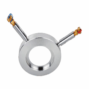
Temperature sensors (T1 and T2):
Supply voltage: NA
Cable: No cable, but with quick-connector
Signal output: Resistive
Media temperature: -20°C to +120°C / -4° to +248°F
Working pressure: 40 bar / 580 psi
Housing material: 304 stainless steel
Protection: IP65
Probe length: 12.7 mm / 0.5 in
Probe diameter: 6 mm / 0.236 in
CE conformity: Yes
Connection: 1/4” ISO
Performance data:
– Sensor type: PT1000
– Accuracy: 0.5% FS (Full Scale)
– Linearity: ±0.5% FS (Full Scale)
– Long time stability: 0.1% FS (Full Scale)
– Response time: at 50°C (122°F): 2.3 sec / at 90°C (194°F): 5.4 sec.
Pressure sensors (P1 and P2):
Supply voltage: 12V DC
Cable: No cable, but with quick-connector
Output: 4-20mA
Media temperature: -10°C to +85°C / 14°F to +185°F
Pressure range2
: 0-25 bar / 0-360 psi
Housing material: 304 stainless steel
Protection: IP65
CE conformity: Yes
Connection: 1/4” ISO
Performance data:
– Accuracy: ±1.5% FS (Full Scale)
(tolerances can be software compensated in the Maplef
Intelligent Interface)
– Stability: 0.5% FS (Full Scale) ±0.05%
– Thermal effect on zero: ±0.1% FS (Full Scale)
– Thermal effect on span: ±0.05% FS (Full Scale)
– Electronic proof: Short circuit protection
– Response time: <20 msec (20 sec mean value calculated in the Maplef
Intelligent Interface)
GENERAL SPECIFICATIONS
1. PRESSURE INDEPENDENT TEMPERATURE CONTROL SYSTEM
1.1. Contractor shall install where indicated in drawings.
1.2. System shall include a Pressure independent dynamic control valve, a sensor kit and an electronic unit.
1.2.1. The PICV valve shall accurately control flow independent of system pressure fluctuations.
1.2.2. The sensor kit shall include 2 temperature sensors and 2 pressure sensors. Temperature sensors
shall measure the ΔT across the coil and pressure sensors shall measure the ΔP across the PICV.
1.2.3. The intelligent interface shall accurately change PICV flow to maintain target ΔT. In addition, the
electronic unit shall calculate BTU heat transfer and supply continuous information on ΔT, ΔP and flow.
2. VALVE ACTUATOR
2.1. Valve-actuator coupling shall be snap coupling for fast mounting and de-mounting.
2.2. Actuator housing shall be rated to IP54 including upside-down mounting.
2.3. Actuator shall be driven by a 24V AC/DC motor and shall accept 2-10V DC electric input signal.
2.4. Actuator shall be capable of providing linear feedback signal to the control system. Feedback signal shall
be equal to input signal, 2-10V DC.
2.5. Automatic calibration of valve position shall be standard.
2.6. Actuator shall include buttons for external programming of all settings.
2.7. Actuator display showing current valve flow, maximum valve flow, input signal, feedback signal and operational
direction shall be standard.
2.8. Optional failsafe versions to power valve to either open (max. setting) or closed position from any position
in case of power failure shall be available.
2.9. Optional BACnet versions shall be available. BACnet versions shall provide remote setting and control of
actuator.
3. VALVE HOUSING
3.1. Housing shall consist of ductile iron ASTM A395 Grade 60-40-18 rated at no less than 4000 kPa (580 psi)
static pressure and +120°C (+248°F).
3.2. Housing shall be permanently marked to show direction of flow.
3.3. Housing shall be for installation between flanges.
3.4. Dual pressure/temperature test plugs for verifying accuracy of flow performance shall be standard on all valve
sizes.
3.5. Identification label according to PED-requirements shall be available for all valves.
4. FLOW REGULATOR / AUTOMATIC BALANCING UNIT
4.1. Maximum flow setting shall be adjustable to 51 different settings within the range of the valve size.
4.2. Flow regulation unit shall be manufactured of stainless steel and hydrogenated acrylonitrile-butadienerubber
and shall be capable of controlling flow within ±5% of controlled flow rate or ±2% of maximum flow rate.
4.3. Flow regulation unit shall be accessible for change-out or maintenance.
5. INTELLIGENT INTERFACE / ELECTRONIC UNIT
5.1. Intelligent interface shall consist of UL94 V0-rated plastic.
5.2. Intelligent interface shall be rated to IP54 including upside-down mounting.
5.3. Intelligent interface shall be driven by 24V AC/DC.
5.4. Intelligent interface shall be Bluetooth® enabled.
5.5. Intelligent interface shall be capable of communicating via BACnet with the control system and wireless
feedback signal to handheld devices. Shall communicate with both Android and iPhone devices and display
via App.
6. TEMPERATURE SENSOR
6.1. Temperature sensors shall consist of 304 stainless steel.
6.2. Temperature sensors shall be IP65.
6.3. Temperature sensors shall provide a resistive output signal corresponding to water temperature.
7. PRESSURE SENSOR
7.1. Pressure sensors shall consist of 304 stainless steel.
7.2. Pressure sensors shall IP65.
7.3. Pressure sensors shall be driven by 12V DC.
7.4. Pressure sensors shall provide a 4-20mA output signal corresponding to water pressure